 Henan Xuye Machinery Equipment Co., Ltd.
SEARCH WHAT YOU WANT
Search allProductNews
SEARCH
The Sludge Rotary Dryer is a heavy-duty, continuous drying system engineered to reduce the moisture content of municipal sewage sludge, industrial wastewater treatment sludge, and other biosolid materials from a wet, mechanically dewatered cake state down to a dry, stable, low-moisture product suitable for landfill volume reduction, fertilizer/soil amendment production, fuel pellet manufacturing, or co-incineration feedstock. As sludge disposal costs continue to rise and landfill capacity tightens in many regions, thermal drying has become one of the most effective strategies available to wastewater treatment plants and industrial facilities for cutting sludge volume, reducing transportation and disposal costs, and converting a waste liability into a usable, sometimes revenue-generating end product.
We supply sludge rotary dryers sized to match capacity requirements ranging from small municipal treatment plants to large-scale industrial and regional biosolids processing facilities. This page covers the working principle, construction and design features, technical specifications, application scenarios, heat source options, and selection guidance to help you determine the right dryer configuration for your sludge management process.
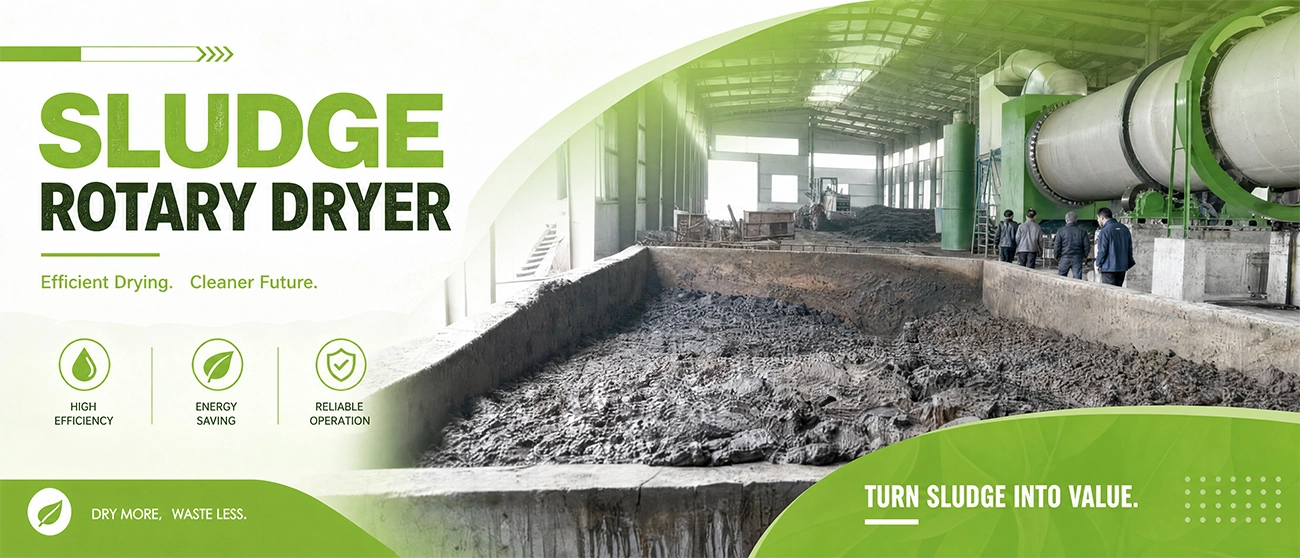
Sludge generated from municipal wastewater treatment and industrial process water treatment typically leaves mechanical dewatering equipment (belt presses, centrifuges, or filter presses) at a moisture content of roughly 75-85%, even after dewatering. This remaining moisture content presents several significant operational and financial challenges:
A properly sized sludge rotary dryer addresses these challenges directly, reducing sludge moisture content — often to below 10-20%, depending on the target end use — in a continuous, high-throughput process that dramatically cuts disposal volume and weight while opening up beneficial reuse pathways that aren’t available for wet sludge cake.
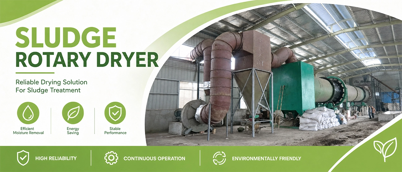
A sludge rotary dryer consists of a slightly inclined, slowly rotating cylindrical drum fitted with internal lifting flights specifically engineered to handle the sticky, cohesive, and variable physical characteristics of dewatered sludge cake — a material that behaves quite differently from free-flowing granular materials and requires specialized design consideration throughout the drying process.
1. Sludge Cake Feed — Mechanically dewatered sludge cake, typically at 75-85% moisture content, is fed into the drum’s inlet end via a screw conveyor or similar metering feed system designed to handle sticky, cohesive cake material without bridging or clogging. In many system designs, a portion of already-dried product is blended back with incoming wet cake before entering the drum (a technique known as back-mixing or recycle blending) to reduce the incoming material’s stickiness and improve its handling and drying behavior — this is a particularly important design consideration specific to sludge drying, distinguishing it from drying free-flowing materials like wood chips or grain.
2. Tumbling and Lifting Action — As the drum rotates, internal lifting flights — designed with sludge’s sticky, cohesive properties specifically in mind — lift and shower the material through the passing hot air/gas stream. Flight design for sludge drying differs meaningfully from flight design for free-flowing granular materials, since sludge cake (especially in its early, wettest drying stage) tends to clump, stick to flight surfaces, and resist the clean showering action achieved with drier, more granular materials.
3. Heat and Moisture Transfer — Hot drying gas, generated by a dedicated heat source, passes through the drum and evaporates moisture from the tumbling sludge material as it travels the drum’s length. As drying progresses and the material’s moisture content decreases, its physical behavior transitions from sticky, cohesive cake to a more granular, free-flowing dried product — a transition that well-designed flight configurations and drum zoning are engineered to accommodate throughout the material’s residence time in the dryer.
4. Discharge and Air Handling — Dried sludge product exits the drum at the discharge end, where a portion may be diverted for recycle/back-mixing with incoming wet cake (as described above), while the remainder proceeds to downstream handling — cooling, screening, storage, pelletizing, or direct transport for disposal or beneficial reuse. Exhaust air, carrying evaporated moisture, odor compounds, and fine particulate, is directed through dust collection equipment (cyclone separators and/or bag filters) and, in many sludge drying system designs, an odor control system — such as a thermal oxidizer, biofilter, or wet scrubber — given the specific odor management requirements associated with sludge processing that are less critical in other biomass or industrial drying applications.
Because sludge cake’s sticky, cohesive behavior in the early drying stage differs substantially from free-flowing granular or fibrous materials, internal flight geometry for sludge rotary dryers is a specialized engineering consideration. Flight designs commonly incorporate features to actively break up clumped material, resist sticking and buildup on flight surfaces, and manage the material’s changing physical behavior as it transitions from wet cake to dried granular product across the drum’s length.
Many sludge drying systems incorporate a dedicated recycle system that blends a controlled proportion of already-dried product back with incoming wet sludge cake before or at the point of drum entry. This back-mixing reduces the moisture content and stickiness of the material entering the drum, improving feed handling reliability, reducing the risk of material buildup and blockages, and supporting more consistent, controllable drying performance — a design feature that is standard practice across most well-engineered sludge drying systems.
The rotating drum shell is fabricated from heavy-gauge carbon steel plate, reinforced as needed to withstand the mechanical loading of the material bed, internal flighting, and continuous rotational operation. Given sludge’s corrosive and sometimes chemically variable characteristics depending on its source (municipal versus specific industrial wastewater streams), material selection and any protective lining requirements should be evaluated based on your specific sludge chemistry.
The loaded drum rests on precision-machined riding rings supported by roller assemblies distributed along the drum’s length, enabling smooth, low-friction rotation while evenly distributing the substantial rotating weight of the drum, internal flighting, and material bed across the support structure.
The drum is rotated via a girth gear and pinion arrangement or friction drive configuration, sized to the torque requirements of the specific drum diameter, length, and loaded material weight, with variable-speed drive control allowing operators to adjust rotational speed and residence time in response to sludge feed characteristics that can vary meaningfully depending on upstream wastewater treatment process conditions and seasonal factors.
Given the specific odor generation characteristics of sludge processing, sludge rotary dryer systems are commonly designed with integrated or downstream odor control equipment — thermal oxidizers (which can also serve double duty as VOC/odor destruction and, in some configurations, as a heat source for the drying process itself), biofilters, or wet chemical scrubbers — selected based on local air quality regulatory requirements and the facility’s specific odor management priorities relative to surrounding land use.
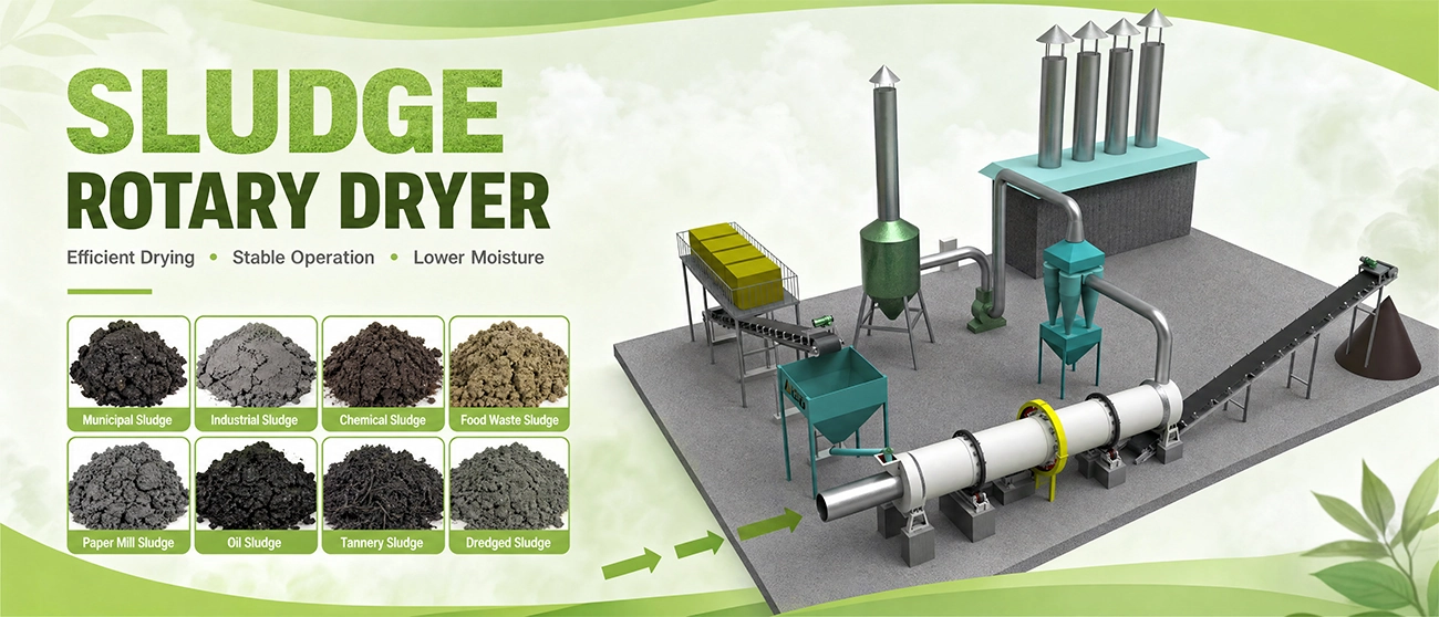
Municipal sewage sludge (biosolids) drying is one of the largest application areas for sludge rotary dryers, where treatment plants seek to reduce sludge volume for disposal cost savings, meet increasingly strict landfill and land application regulations, and, where local agricultural markets and regulatory frameworks support it, produce a dried biosolids product suitable for beneficial reuse as an agricultural soil amendment or fertilizer component.
Industrial facilities across chemical manufacturing, food and beverage processing, pulp and paper, textile, and other sectors generate process wastewater sludge with characteristics specific to their industry and process chemistry. Rotary drying reduces disposal volume and cost for these industrial sludge streams, with dryer sizing and material selection tailored to the specific sludge chemistry and contamination profile involved.
Where local regulations and agricultural markets support beneficial reuse, dried municipal biosolids can be further processed — often pelletized — into a marketable fertilizer or soil amendment product, converting a disposal cost center into a revenue-generating byproduct stream. Achieving the moisture, pathogen reduction, and physical handling characteristics required for this end use is a key design driver for the drying system.
Dried sludge with sufficient calorific value can be processed into a solid fuel product used as a supplementary fuel in cement kilns, industrial boilers, or dedicated waste-to-energy facilities, providing an alternative disposal pathway that recovers energy value from the material rather than simply landfilling it.
Facilities preparing sludge as feedstock for co-incineration or dedicated sludge incineration processes use rotary drying to reduce moisture content ahead of combustion, improving combustion stability and net energy balance compared to attempting to combust high-moisture sludge cake directly.
Even where beneficial reuse is not pursued, thermal drying substantially reduces the weight and volume of sludge requiring landfill disposal, directly reducing transportation costs (often the dominant cost factor for facilities located at a distance from disposal sites) and landfill tipping fees charged on a per-ton basis.
| Model | Cylinder diameter(mm) | Cylinder length(mm) | Cylinder volume(m3) | Cylinder rotary speed (r/min) | Power(kW) | Weight(t) |
| 0.6×5.8 | 600 | 5800 | 1.7 | 1-8 | 3 | 2.9 |
| 0.8×8 | 800 | 8000 | 4 | 1-8 | 4 | 3.5 |
| 1×10 | 1000 | 10000 | 7.9 | 1-8 | 5.5 | 6.8 |
| 1.2×5.8 | 1200 | 5800 | 6.8 | 1-6 | 5.5 | 6.7 |
| 1.2×8 | 1200 | 8000 | 9 | 1-6 | 5.5 | 8.5 |
| 1.2×10 | 1200 | 10000 | 11 | 1-6 | 7.5 | 10.7 |
| 1.2×11.8 | 1200 | 11800 | 13 | 1-6 | 7.5 | 12.3 |
| 1.5×8 | 1500 | 8000 | 14 | 1-5 | 11 | 14.8 |
| 1.5×10 | 1500 | 10000 | 17.7 | 1-5 | 11 | 16 |
| 1.5×11.8 | 1500 | 11800 | 21 | 1-5 | 15 | 17.5 |
| 1.5×15 | 1500 | 15000 | 26.5 | 1-5 | 15 | 19.2 |
| 1.8×10 | 1800 | 10000 | 25.5 | 1-5 | 15 | 18.1 |
| 1.8×11.8 | 1800 | 11800 | 30 | 1-5 | 18.5 | 20.7 |
| 1.8×15 | 1800 | 15000 | 38 | 1-5 | 18.5 | 26.3 |
| 1.8×18 | 1800 | 18000 | 45.8 | 1-5 | 22 | 31.2 |
| 2×11.8 | 2000 | 11800 | 37 | 1-4 | 18.5 | 28.2 |
| 2×15 | 2000 | 15000 | 47 | 1-4 | 22 | 33.2 |
| 2×18 | 2000 | 18000 | 56.5 | 1-4 | 22 | 39.7 |
| 2×20 | 2000 | 20000 | 62.8 | 1-4 | 22 | 44.9 |
| 2.2×11.8 | 2200 | 11800 | 44.8 | 1-4 | 22 | 30.5 |
| 2.2×15 | 2200 | 15000 | 53 | 1-4 | 30 | 36.2 |
| 2.2×18 | 2200 | 18000 | 68 | 1-4 | 30 | 43.3 |
| 2.2×20 | 2200 | 20000 | 76 | 1-4 | 30 | 48.8 |
| 2.4×15 | 2400 | 15000 | 68 | 1-4 | 30 | 43.7 |
| 2.4×18 | 2400 | 18000 | 81 | 1-4 | 37 | 53 |
| 2.4×20 | 2400 | 20000 | 91 | 1-4 | 37 | 60.5 |
| 2.4×23.6 | 2400 | 23600 | 109 | 1-4 | 45 | 69.8 |
| 2.8×18 | 2800 | 18000 | 111 | 1-3 | 45 | 62 |
| 2.8×20 | 2800 | 20000 | 123 | 1-3 | 55 | 65 |
| 2.8×23.6 | 2800 | 23600 | 148 | 1-3 | 55 | 70 |
| 2.8×28 | 2800 | 28000 | 172 | 1-3 | 75 | 75 |
| 3×20 | 3000 | 20000 | 14 | 1-3 | 55 | 75 |
| 3×23.6 | 3000 | 23600 | 170 | 1-3 | 75 | 85 |
| 3×28 | 3000 | 28000 | 198 | 1-3 | 90 | 91 |
| 3.2×23.6 | 3200 | 23600 | 193 | 1-3 | 90 | 112 |
| 3.2×32 | 3200 | 32000 | 257 | 1-3 | 110 | 129 |
| 3.6×36 | 3600 | 36000 | 366 | 1-3 | 132 | 164 |
| 3.8×36 | 3800 | 36000 | 408 | 1-3 | 160 | 187 |
| 4×36 | 4000 | 36000 | 452 | 1-3 | 160 | 195 |